
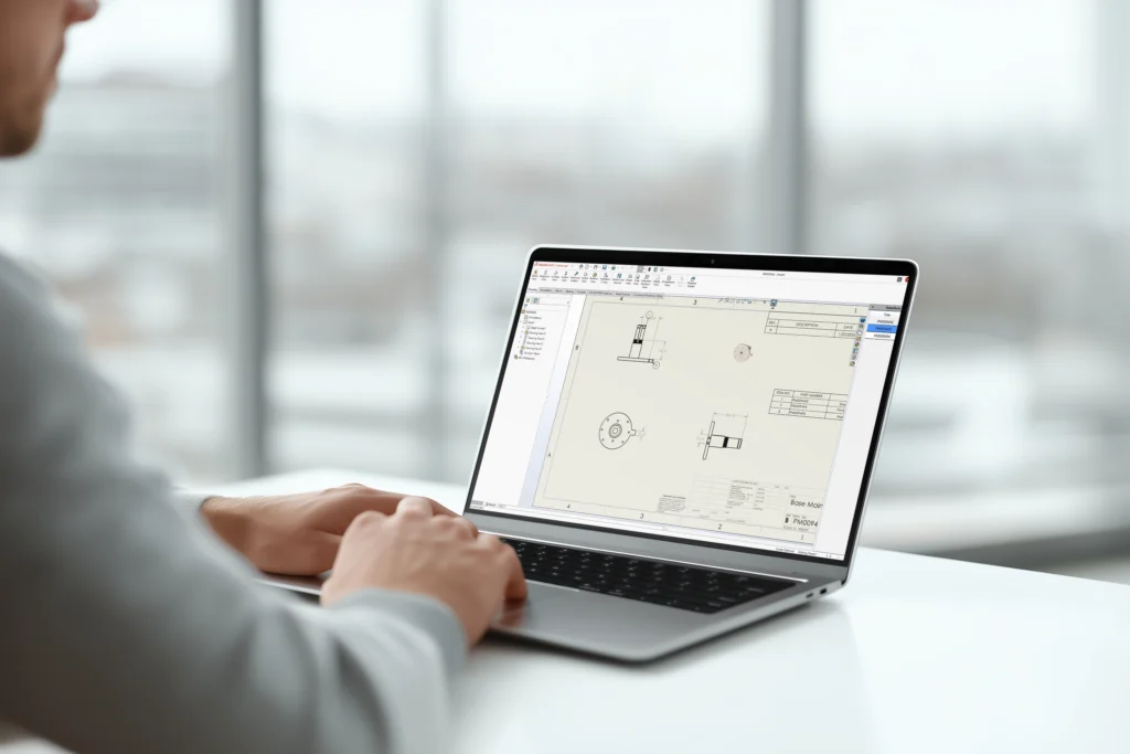
Your 3D model might be perfect. Every fillet, every hole, every edge exactly where it should be. But if the drawing that reaches the shop floor is messy, confusing, or missing key details, none of that matters.
Engineering drawings are still the main way most manufacturers communicate what needs to be made, how it should be measured, and what tolerances apply. Even with 3D viewers becoming more common, the 2D drawing remains the governing reference in most production environments.
SOLIDWORKS Design gives you a full set of tools for creating these drawings directly from your 3D parts and assemblies. This guide covers how to set them up properly, use them efficiently, and avoid the common mistakes that make drawings harder to read than they need to be.
What Are SOLIDWORKS Drawing Tools and Why Do Engineers Use Them?
SOLIDWORKS drawing tools are the built-in features that let you create 2D engineering drawings from 3D parts and assemblies. Every drawing stays associatively linked to its source model, so when the design changes, dimensions, views, and annotations update automatically.
The toolset covers the full documentation workflow. You can insert standard and projected views, create section and detail views, add dimensions and tolerances, place GD&T symbols, generate bills of materials, and annotate with notes, callouts, and surface finish symbols.
These tools are included in every version of SOLIDWORKS. You don’t need a separate application or add-on for core drawing work.
Setting Up Drawing Templates and Sheet Formats
Before you create a single drawing view, it’s worth getting your templates right. This is the step most teams skip, and it costs them time on every drawing after that.
SOLIDWORKS uses two separate files to control your drawing environment. The drawing template (.drwdot) stores your document settings: drafting standard (ISO, ANSI, etc.), units, font sizes, arrow styles, and projection type. The sheet format (.slddrt) stores your title block, border, and any linked custom properties like part number, material, or drawn-by fields.
Think of it this way: the template is the rulebook, the sheet format is the stationery. You typically want one template with multiple sheet formats for different paper sizes (A3, A4, A1, etc.).
Getting this right upfront means every drawing your team produces will follow the same standards automatically. Font sizes, dimension styles, line weights, and title block information all stay consistent without anyone having to set them manually each time.
Link your title block fields to custom properties in the model. That way, the part number, description, and material fill in automatically when you create a drawing from a part. Less typing, fewer mistakes.
How Do You Add and Arrange Drawing Views?
You add drawing views by dragging a 3D part or assembly onto a drawing sheet. SOLIDWORKS creates a standard three-view layout (front, top, right), and you can add auxiliary, section, detail, and broken-out section views from there.
The most common view types you’ll work with are:
Standard views show your part from defined orientations (front, top, right, isometric). These form the backbone of most drawings. Section views cut through the part along a line you define, revealing internal features like bores, pockets, or wall thicknesses. Detail views zoom into a specific area at a larger scale, which is useful for showing fine features like chamfers, thread callouts, or small radii. Broken-out section views remove a portion of an existing view to expose what’s underneath, without needing a full section cut.
SOLIDWORKS 2025 introduced AI-powered automatic drawing generation through its service pack updates, and SOLIDWORKS 2026 expanded on it with further improvements. You can select one or more parts or assemblies, and the software will determine the best sheet size, insert and scale views, and even generate section views and hole callouts automatically. It’s still in beta, but it provides a solid starting point that you can refine manually.
The key with views is restraint. Include the views you need to fully define the part, but don’t add views that repeat information already shown elsewhere on the drawing.
Dimensions, Tolerances, and Annotations
Dimensions and annotations are what turn a picture of your part into a usable manufacturing document. SOLIDWORKS gives you several tools for this, and choosing the right approach saves time.
Smart Dimension is the tool you’ll reach for most often. Click an edge, a point, or between two features, and SOLIDWORKS places a dimension. It works on lines, arcs, circles, and between geometry in different views.
Model Items is where things get more efficient. Instead of adding every dimension by hand, Model Items pulls dimensions directly from the 3D model into the drawing. If you’ve already defined your key dimensions in the part (and you should), you can import them in one step. This keeps your drawing dimensions tied to the same values your model uses, which avoids mismatches.
For tolerances, you can set default tolerance values in your document properties so every dimension gets the right tolerance format automatically. SOLIDWORKS supports bilateral, unilateral, limit, and fit tolerances. You can override individual dimensions where tighter control is needed.
Beyond dimensions, you’ll use annotations like notes, surface finish symbols, hole callouts, centrelines, and centre marks. Hole callouts are particularly useful because they pull hole size, depth, and thread information straight from the feature definition. One click, and the callout is done.
Keep your annotations organised. Place dimensions on the view that best shows the feature. Avoid stacking dimensions on top of each other, and use ordinate or baseline dimensioning when you have a row of features measured from a common reference.
How Do You Apply GD&T in SOLIDWORKS Drawings?
GD&T (geometric dimensioning and tolerancing) is applied in SOLIDWORKS through the Geometric Tolerance tool under the Annotation tab. You select a GD&T symbol (flatness, perpendicularity, position, etc.), define the tolerance value and any material modifiers, then attach the feature control frame to the relevant geometry on your drawing.
GD&T goes beyond basic plus/minus tolerancing. It controls the form, orientation, and location of features relative to datum references. This matters when parts need to fit together in an assembly, where a simple length tolerance isn’t enough to guarantee the part will work.
SOLIDWORKS supports both the ASME Y14.5 and ISO GPS standards for GD&T. Your drafting standard selection in the document properties determines which symbol set and rules the software follows.
To apply GD&T effectively, start by defining your datum features. Datums are the reference points that everything else is measured from. Place datum symbols on the features that will be used to locate or hold the part during machining or inspection.
Then add your feature control frames. Each frame specifies a geometric characteristic (like position or profile), the tolerance zone, and which datums the tolerance references. You can attach these directly to dimensions or place them independently on the drawing.
SOLIDWORKS also offers DimXpert (now called MBD Dimensions), which can automatically apply a dimensioning scheme to your part. If you want a complete, standards-compliant dimension scheme without building it manually, this tool is worth learning.
Bills of Materials and Assembly Drawing Tools
When you create a drawing from an assembly, you’ll typically need a bill of materials (BOM), balloons, and possibly a revision table.
SOLIDWORKS generates a BOM directly from your assembly structure. It lists every component, including part numbers, descriptions, quantities, and materials. You choose between a top-level BOM (showing only first-level components) or an indented BOM (showing sub-assemblies and their contents). If your assembly includes weldments or sheet metal parts, cut lists can appear as separate items.
Balloons connect each item in the BOM to its location in the drawing. Auto-balloon places them all at once, and you can adjust their position and style afterward. In SOLIDWORKS 2026, magnetic lines now work with more annotation types, including notes, weld symbols, surface finish symbols, and geometric tolerances. This makes it faster to align callouts neatly on the sheet.
Revision tables track drawing changes over time. Each revision gets a letter or number, a description, and a date. This is important for quality control and traceability, especially in regulated industries.
If your team manages a lot of drawings, version control becomes critical. A product data management system like SOLIDWORKS PDM keeps drawing files, revisions, and approvals organised. Our guide to PDM for design teams covers when and why this matters.
How Can You Make SOLIDWORKS Drawings Easier to Read?
If your templates handle the standards (covered earlier), readability comes down to how you lay out the drawing itself.
Layers help you separate different types of information. Put centrelines on one layer, dimensions on another, and notes on a third. This makes it easy to control what’s visible and what prints, especially on busy drawings with a lot of detail.
Spacing matters more than most people think. Dimensions that overlap or crowd each other lead to questions on the shop floor. Space your dimension lines evenly, and use leader lines to pull annotations away from congested areas.
Centrelines and centre marks should appear on every cylindrical feature and pattern. They’re easy to forget, but inspectors and machinists rely on them to locate hole centres and establish symmetry.
SOLIDWORKS delivers drawing enhancements through regular functional delivery updates, so the layout tools keep improving. Dimension line breaks now prevent text from overlapping crossing lines, and they update dynamically when you move a dimension.
One habit worth building: review your drawing as if you’ve never seen the part before. If you can’t figure out what’s being communicated in five seconds, the drawing needs work.
Getting Started with Better Drawings
Good engineering drawings come down to three things: a solid template, the right views, and clear annotations. Invest a few hours in setting up your templates and document properties properly, and every drawing after that will be faster and more consistent.
If you’re already working in SOLIDWORKS and want to sharpen your drawing skills, structured SOLIDWORKS training courses can help you get more from the tools you already have. From template configuration to advanced detailing, our trainers walk you through the workflows that save the most time.
Ready to improve your engineering drawings or explore what SOLIDWORKS can do for your team? Contact the Cadmes team to discuss your needs.